XRP Robot Assembly Guide
Follow this step-by-step guide to assemble your XRP robot. The entire process takes about 15 minutes.
Assembly Video
Watch the complete assembly video, or follow the written instructions below with timestamps to jump to specific sections.
What's in the Kit
Before you begin, make sure you have all the parts from your XRP kit.
The XRP robot uses the same types of components as the LEGO Spike Prime, just in a different form factor. If you've used Spike Prime before, you'll recognize the equivalent parts below:
XRP Component
Spike Prime Equivalent
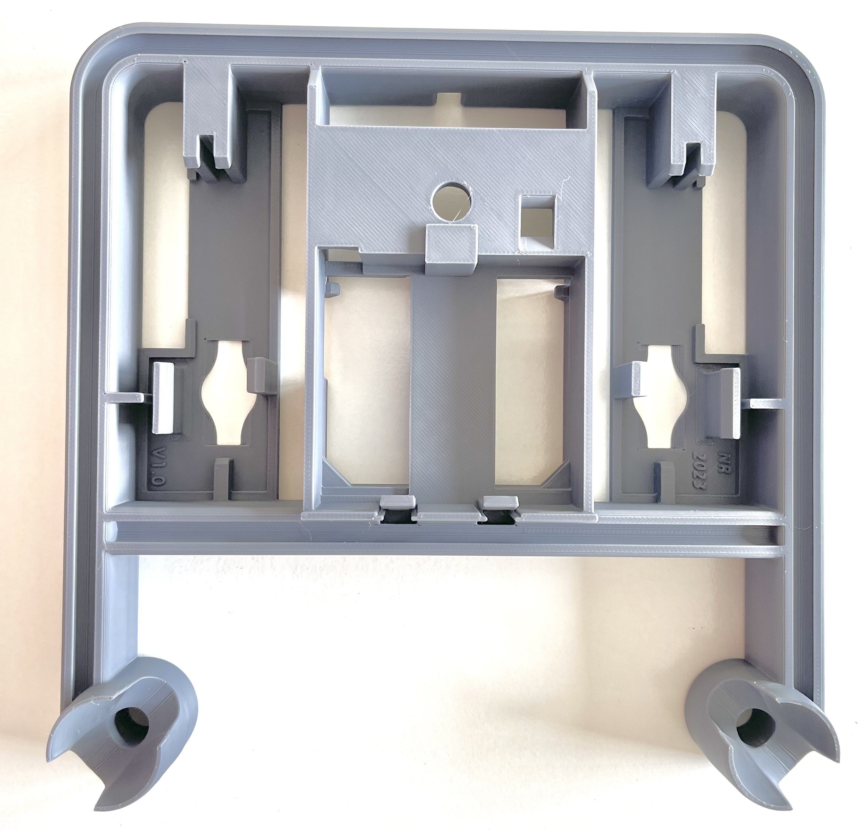
Robot Chassis
Single-piece design with a rail system for easy component attachment.
Spike Chassis
Built from LEGO Technic pieces.
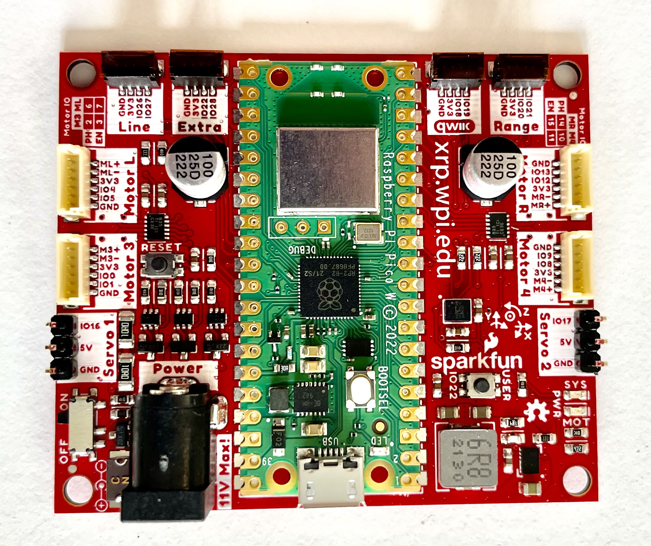
Robot Controller
The brain of your robot with an RP2350 microprocessor.
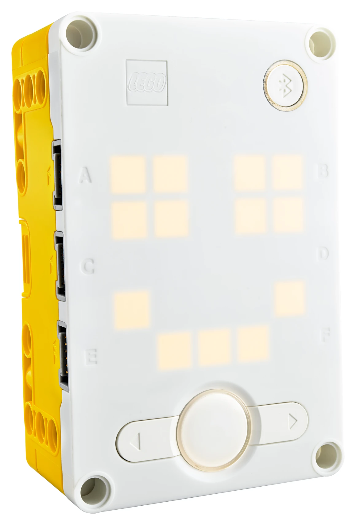
Hub
The programmable brain of the Spike Prime.
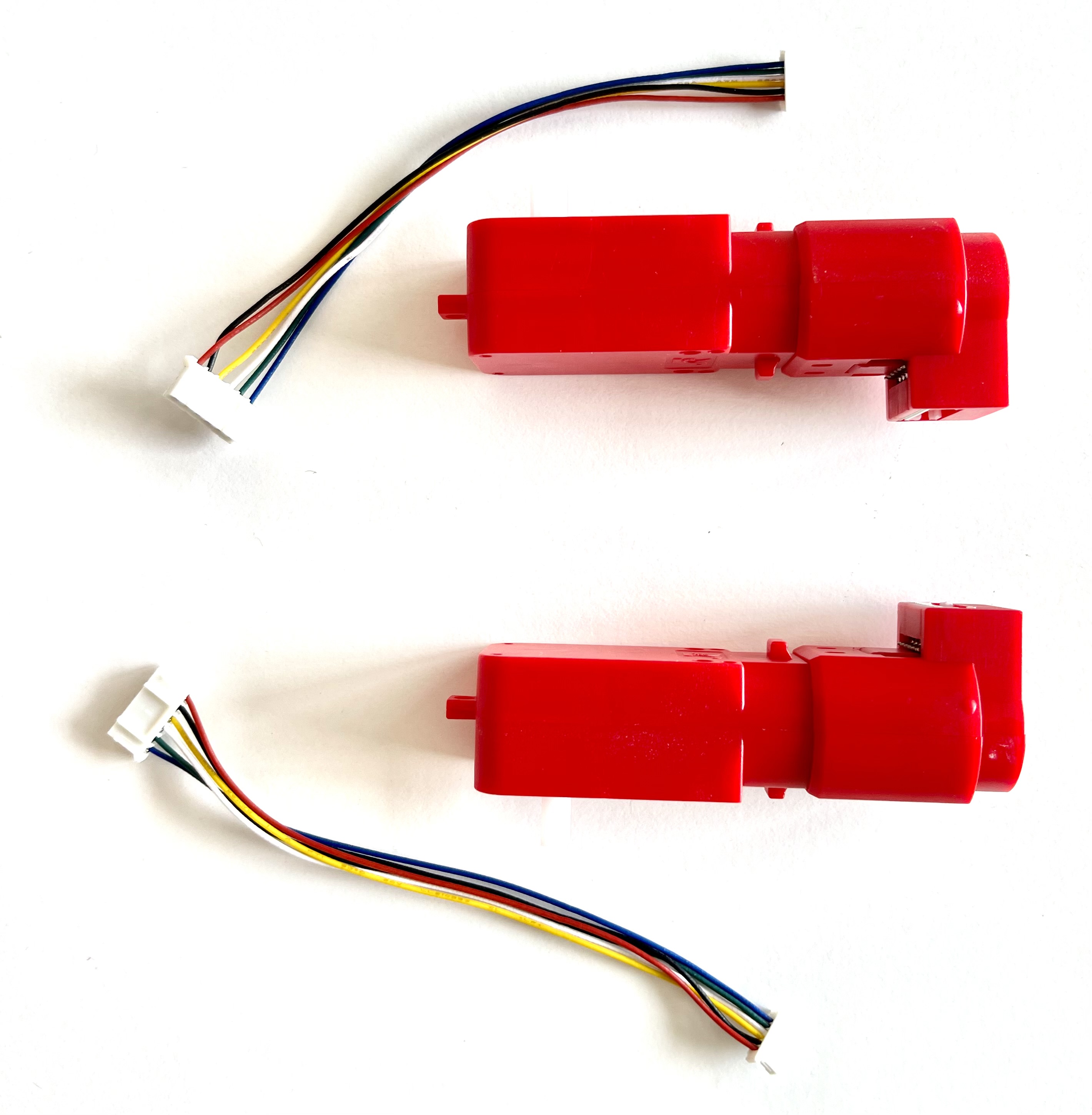
Motors with Encoders
Two motors with built-in sensors to measure wheel rotation.
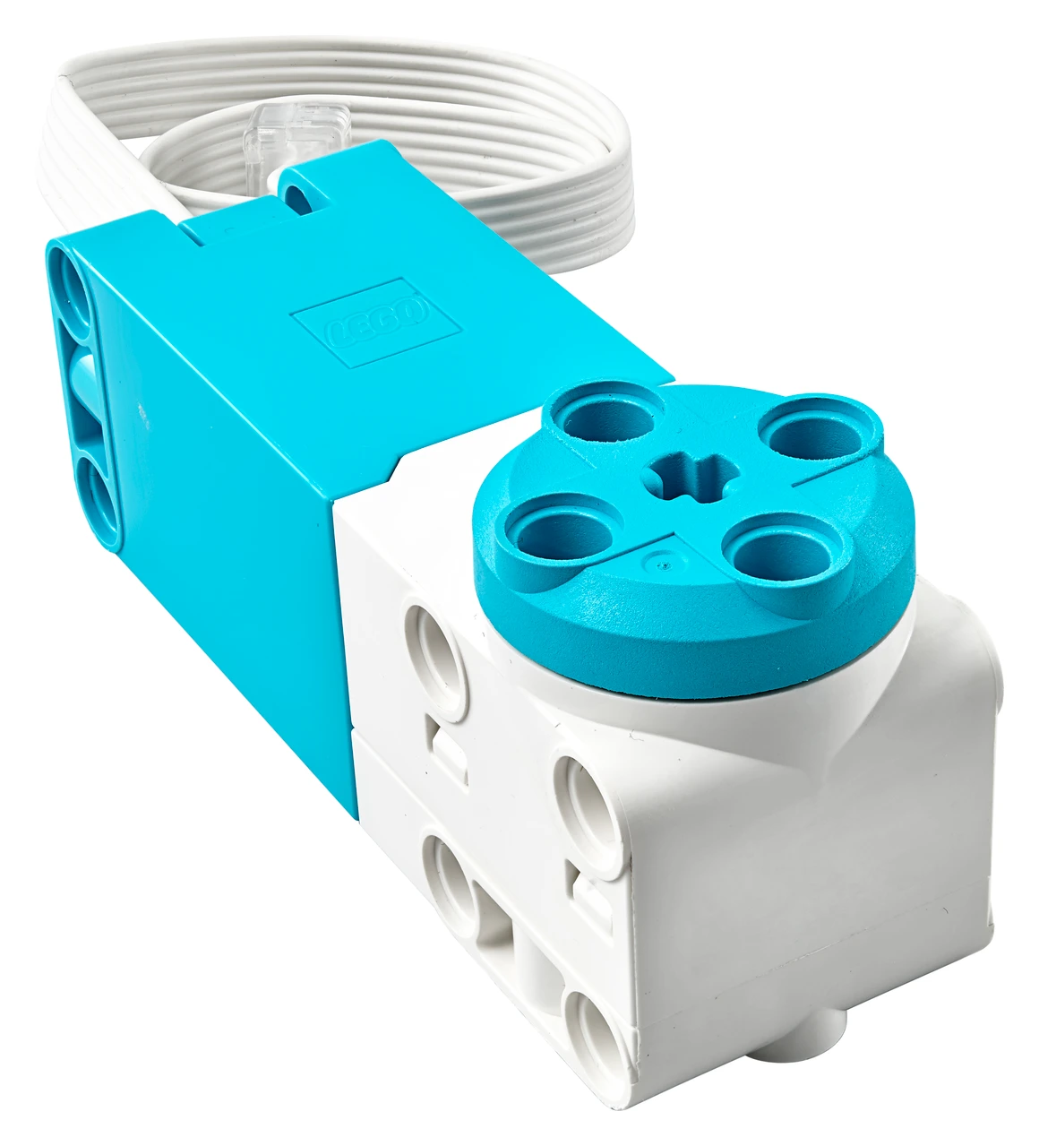
Motor
Spike Prime motors with rotation sensors.
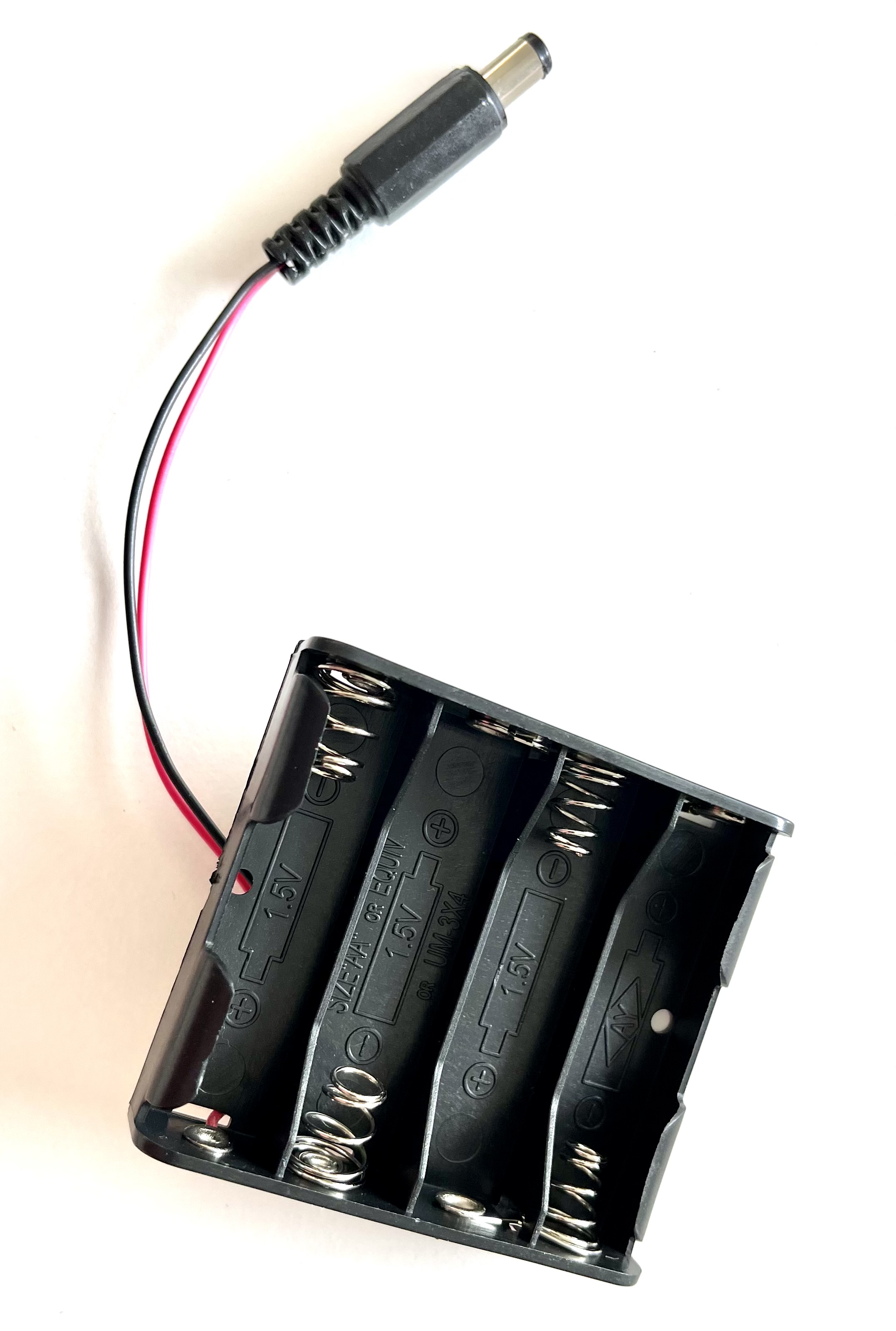
Battery Case
Holds 4 AA batteries. Rechargeable batteries recommended.
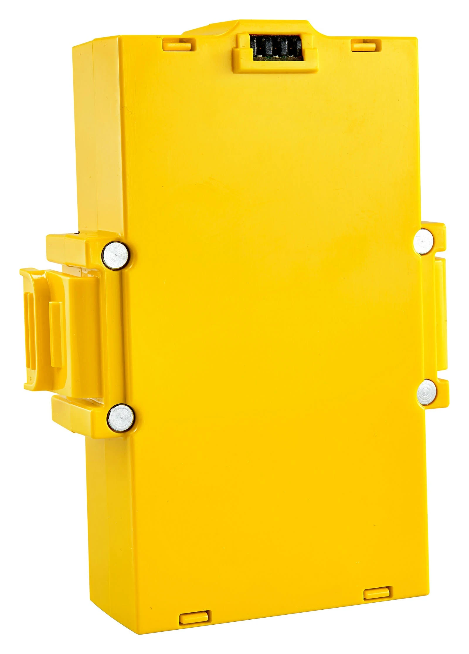
Battery
Built-in rechargeable battery in the Hub.
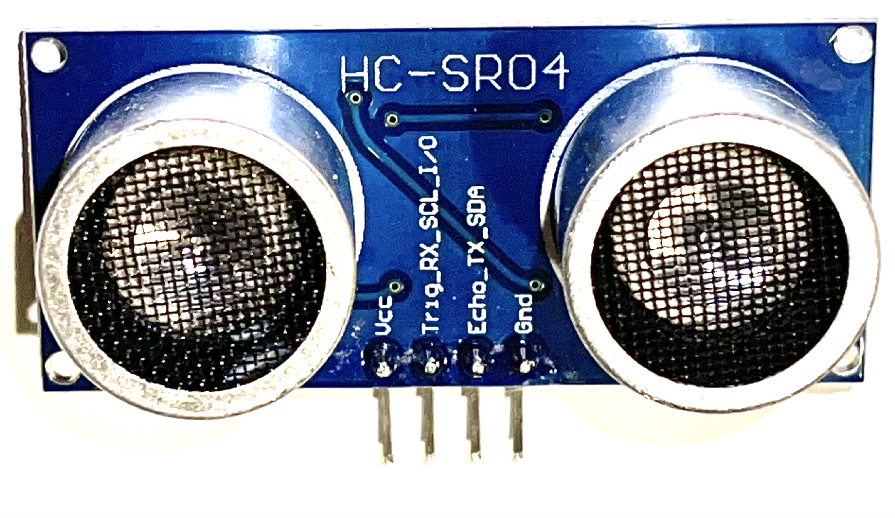
Ultrasonic Rangefinder
Measures distance to objects using sound waves.
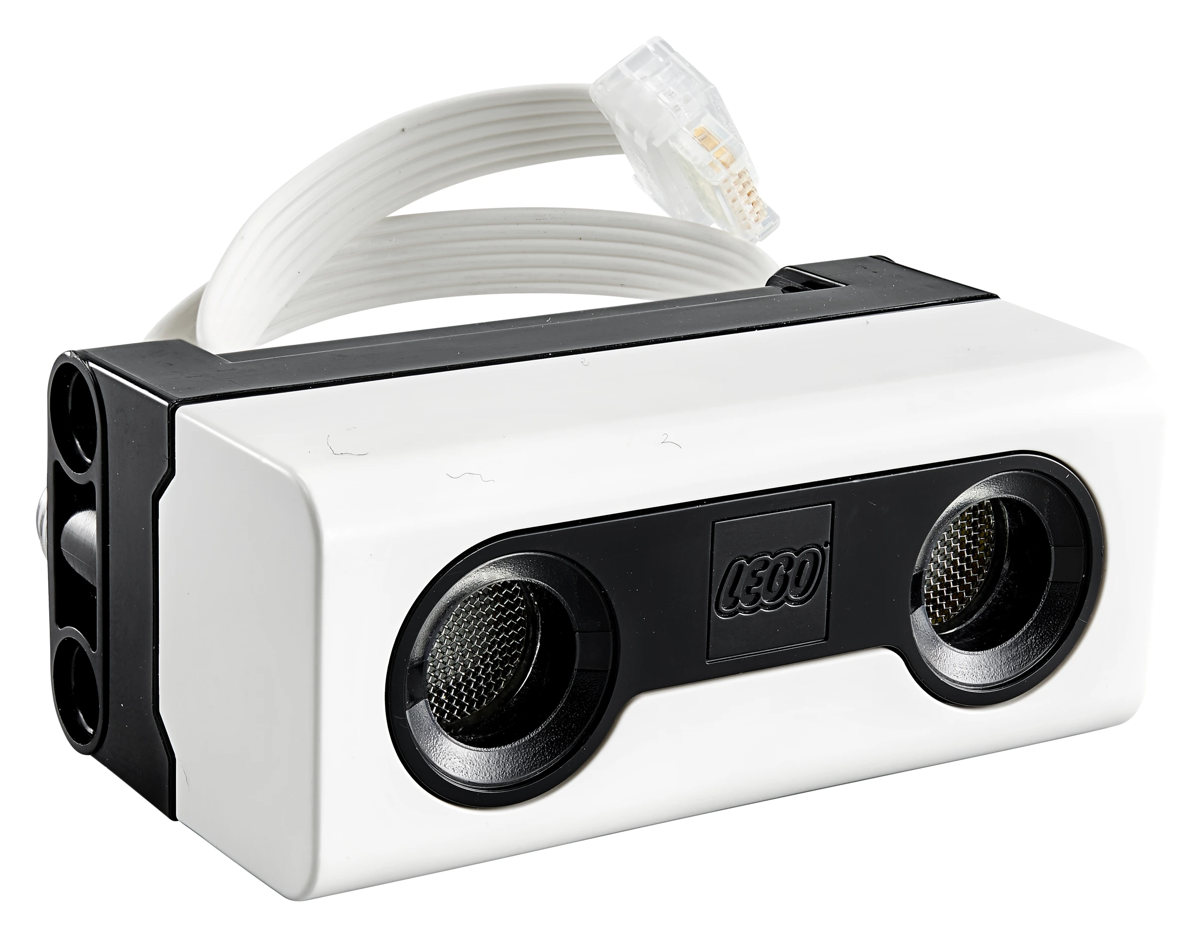
Distance Sensor
Ultrasonic sensor for measuring distance.
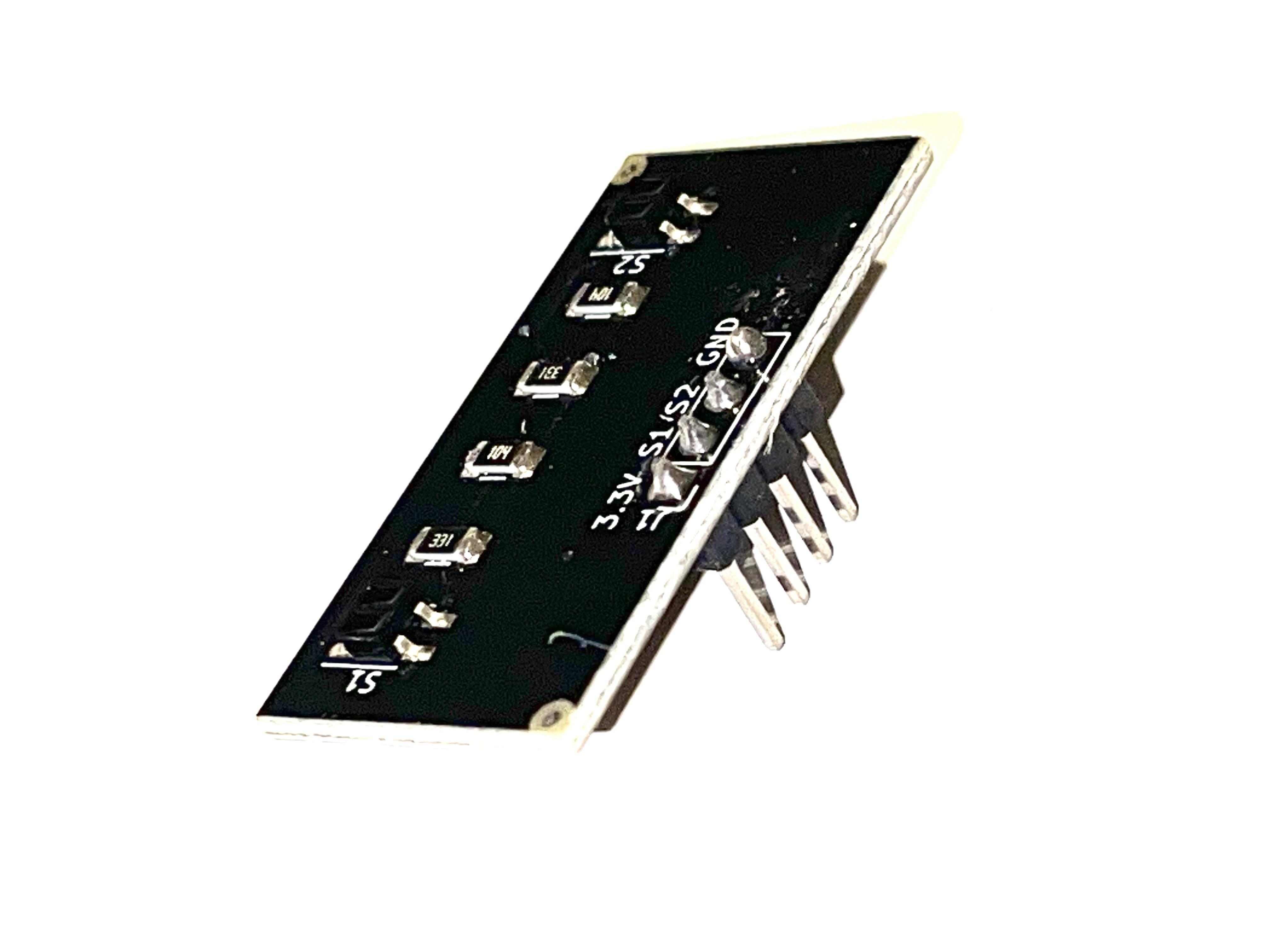
Reflectance Sensor
Detects light and dark surfaces for line following.
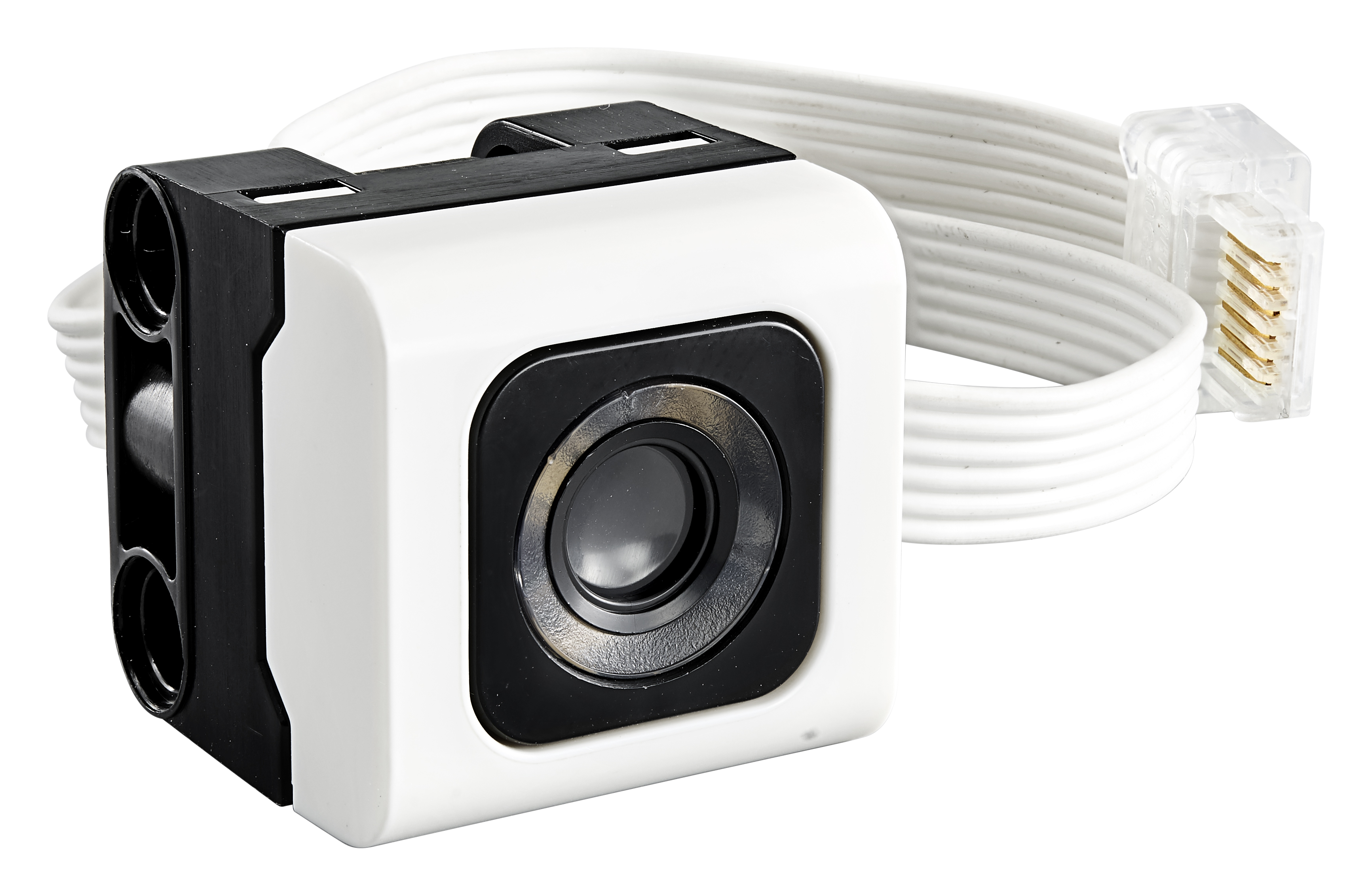
Color Sensor
Detects colors and light intensity.
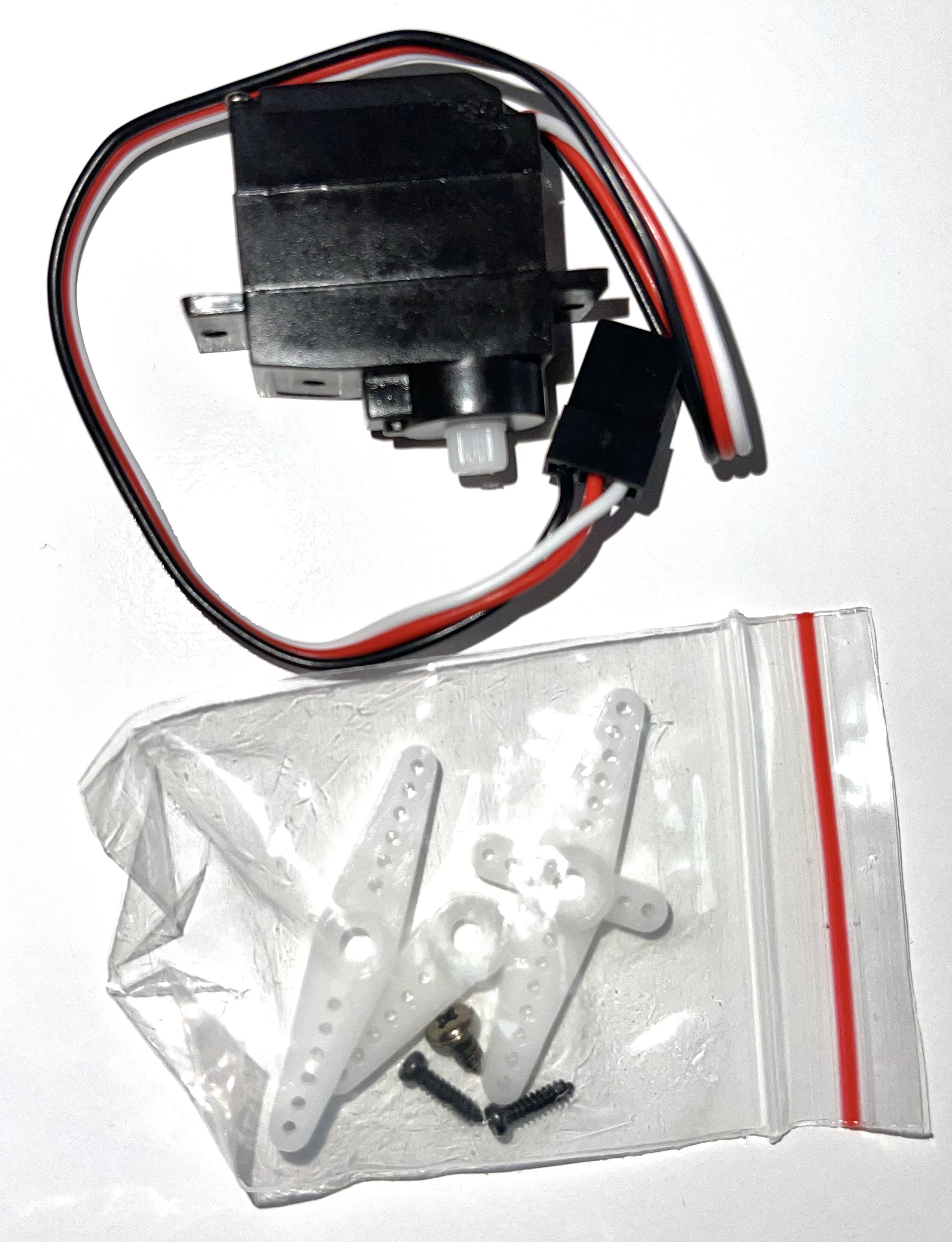
Servo Motor
Moves to preset angles for the robotic arm.
Motor
Spike motors can also move to specific angles.
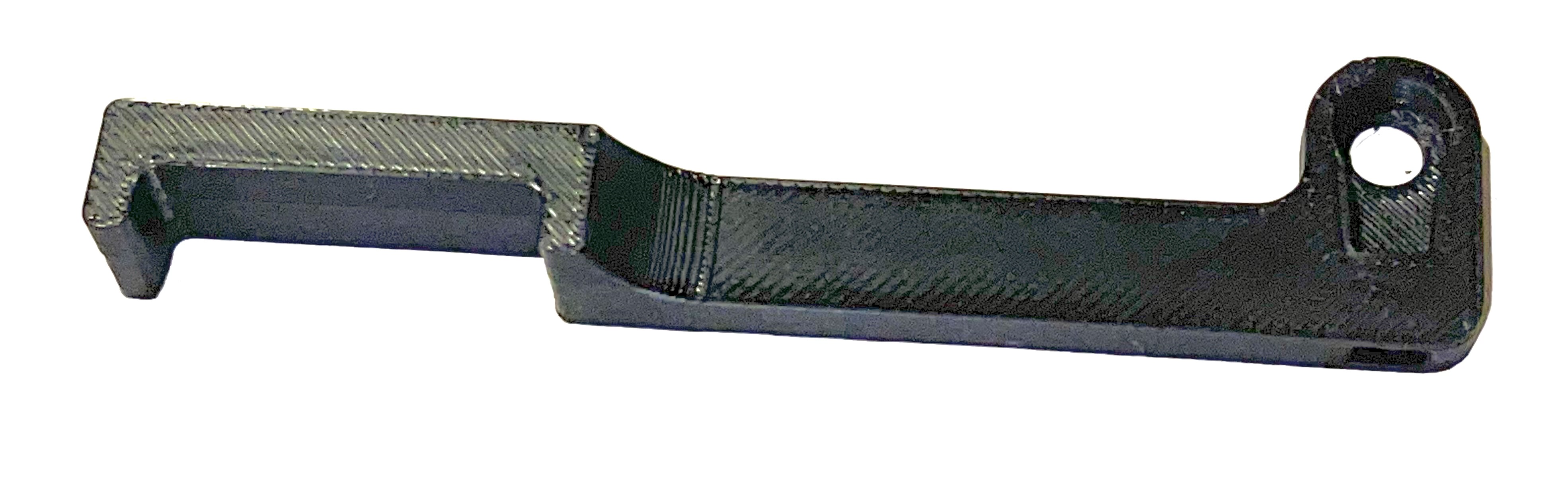
Servo Arm
Attaches to the servo for grabbing or pushing objects.
Attachment
LEGO Technic pieces for building arms and attachments.
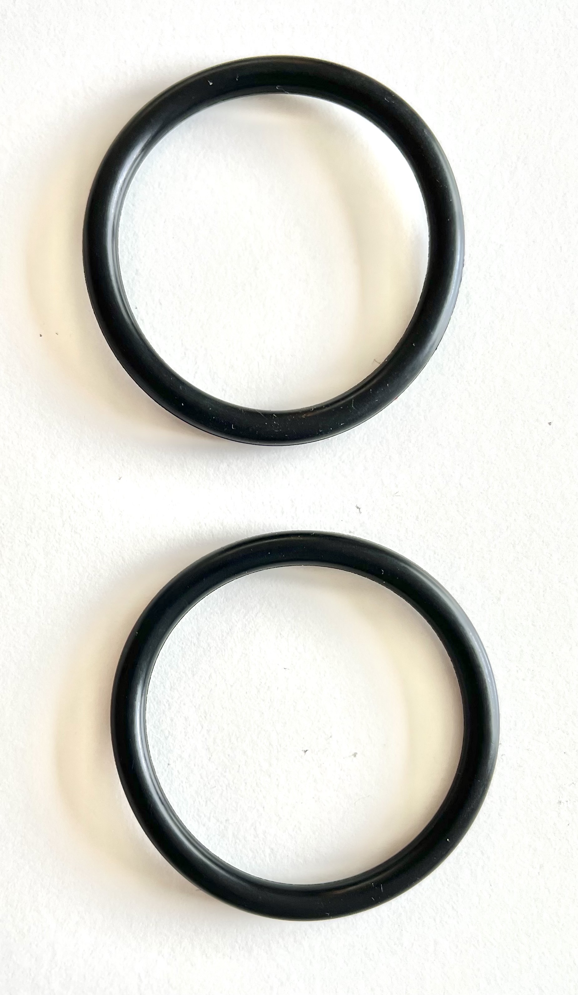
Wheels & Tires
Two wheels with o-ring tires for traction.
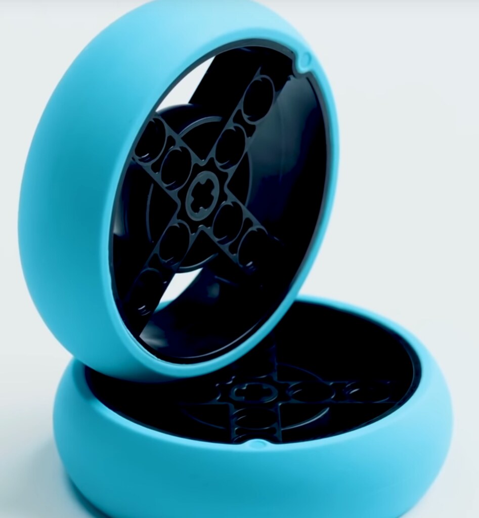
Spike Wheels
LEGO Technic wheels with rubber tires.
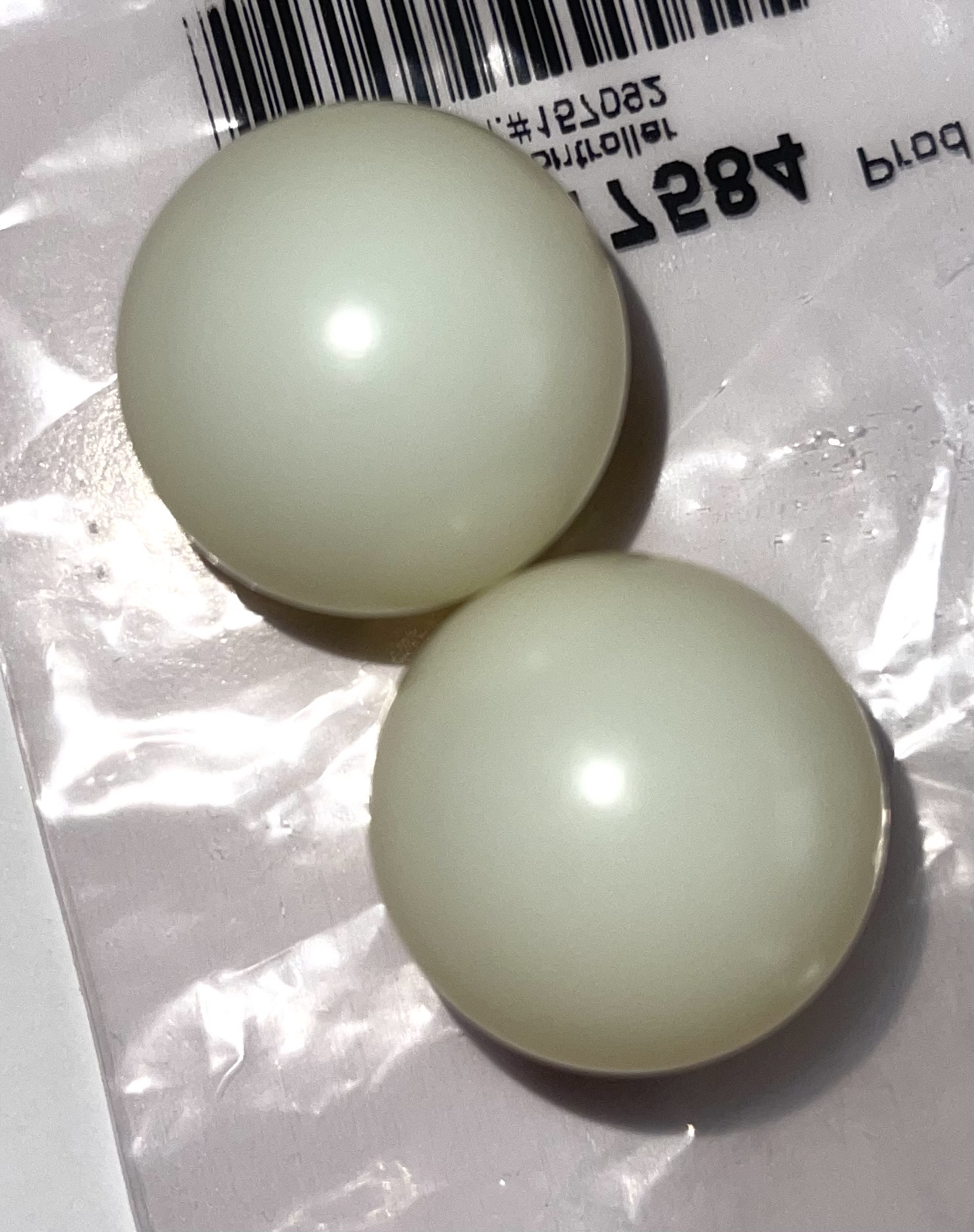
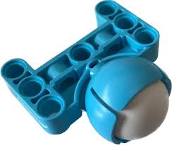
Casters
Two ball casters for the front of the robot.
Spike Casters
Ball casters or wheel-based supports.
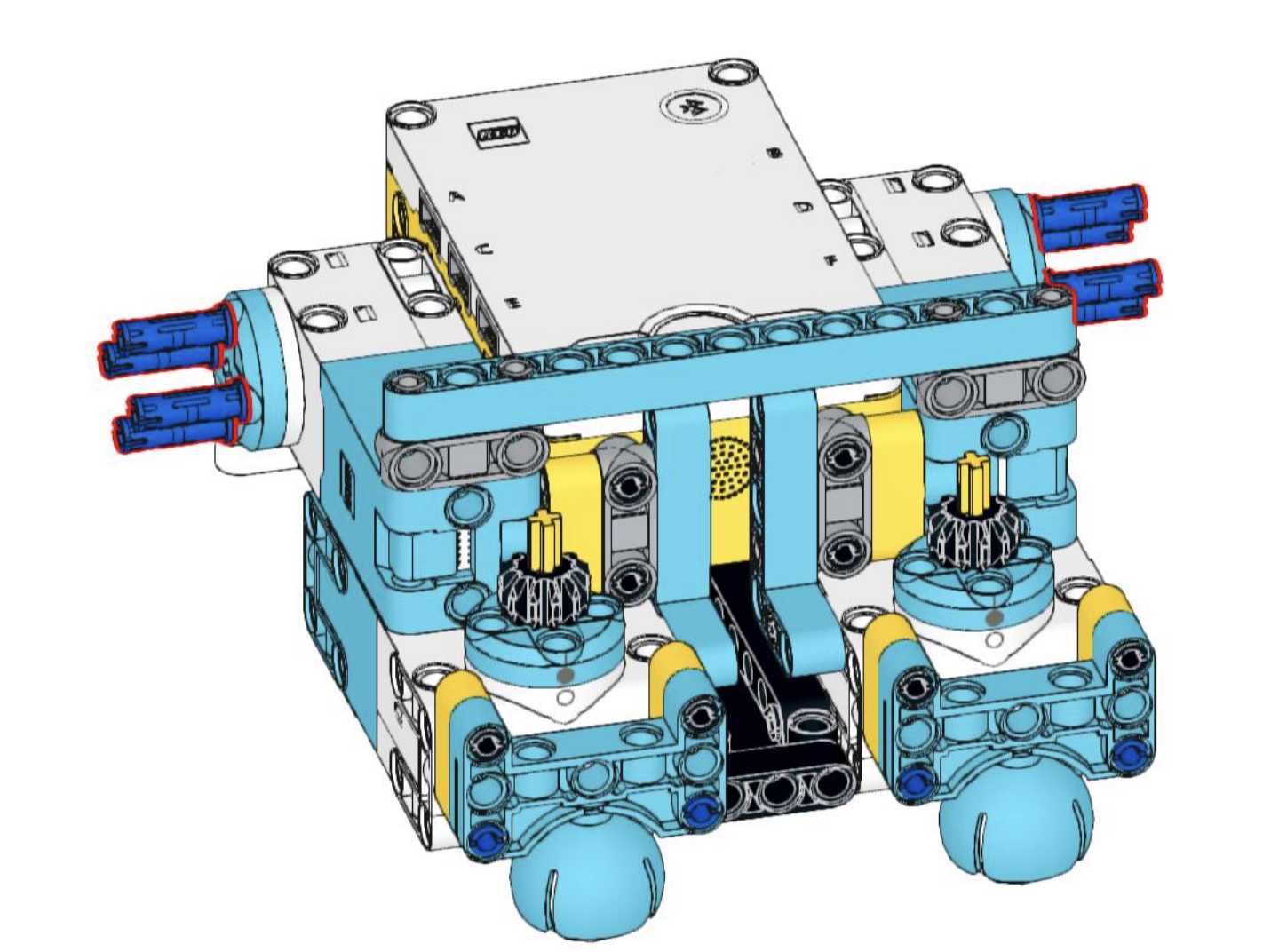
Assembly Steps
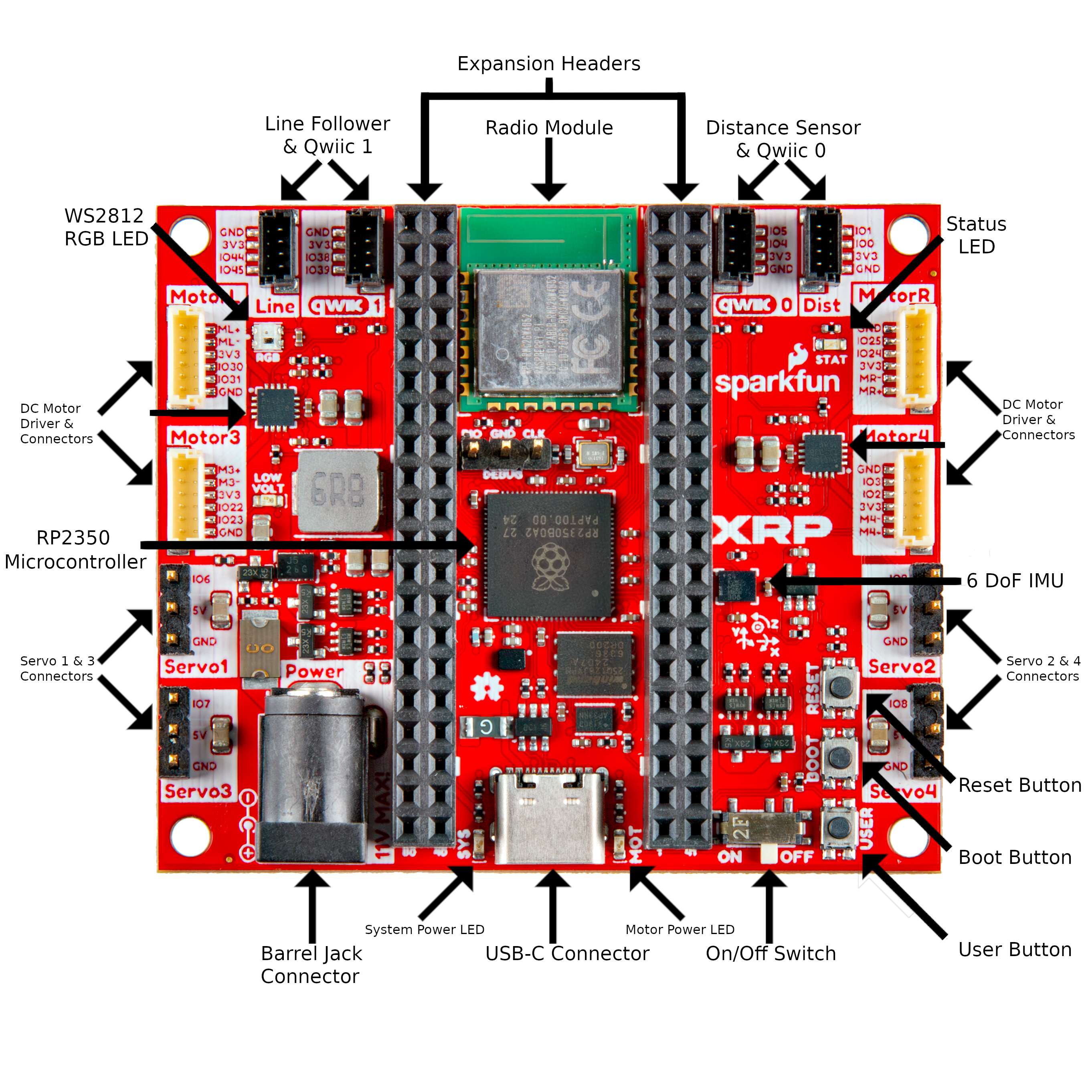
Controller Board Reference
Use this diagram to identify connectors on the robot controller during assembly.
Install the Battery Pack
Flip over the chassis. Orient the battery holder so the wire corner is in the recessed area. Feed the barrel connector through the hole, then snap the holder into place.
Add Batteries and Retention Bar
Install four AA batteries (not included). We recommend rechargeable NiMH batteries. Insert the retention bar into the cutouts to prevent batteries from falling out.
Install the Robot Controller
Remove any Kapton tape from the connectors. Make sure battery wires lie flat. Insert the top corners into the front notches first, then push down near the USB-C connector to seat the board.
Connect Battery Power
Plug in the barrel connector from the battery holder. Optional: Do a quick power test - flip the switch to ON and look for two red power LEDs near the USB connector.
Insert the Casters
Place the 1-inch diameter caster wheels into the front cages. Push straight down to snap them into place.
Mount the Wheels
Press the wheels onto the motor shafts. Align the flat spots on the shaft with the flats in the wheel. Make sure the flat side of the wheel faces outward.
Add the Tires
Slip the rubber O-ring tires over the wheel rims into the grooves. Tip: Seat about half the tire first, then roll the remaining half into place with your thumbs.
Connect Motor Cables to Motors
The large connector goes into the motor. Small bumps align with a cutout so it only fits one way. Push firmly until fully inserted.
Install the Motors
Orient motors so cables point toward the front and wheels face outward. Insert the wheel side first, aligning with the small cutout, then push the front side to snap into place.
Connect Motors to Controller
Connect the left motor to "Motor L" and right motor to "Motor R". Insert connectors straight to avoid bending pins. Red and black wires go to + and - pins.
Wire the Sensors
Connect cables to sensors first. Wire order: black (GND), yellow, blue, red (3.3V). Mnemonic: Black and yellow go next to each other, like honeybee stripes!
Mount Sensor Brackets
Attach the line sensor mount first, aligning the nub with the notch in the bottom rail. Then attach the ultrasonic sensor mount at the front center.
Attach Sensors to Mounts
Insert the line sensor with wires pointing toward the front and top. Insert the ultrasonic sensor facing forward. Insert back/bottom edge first, then snap into place.
Connect Sensors to Controller
Route cables through slots in the chassis front. Connect line sensor to "Line" and ultrasonic to "Dist" connectors. Red/black wires go to 3V3/GND.
Attach Servo Bracket
The servo mount attaches to the back center rail, slightly left of center so the arm will be centered. Insert the nub into the top rail, then push the bottom end to snap into place.
Mount the Servo
Orient the servo so the output shaft faces right and slightly toward the front. Push the servo between the mount arms and press down until it clicks.
Prepare Servo Arm
Select the single-ended horn from the bag. Insert the thin end into the hidden slot in the arm base, flat side down, and push until it snaps.
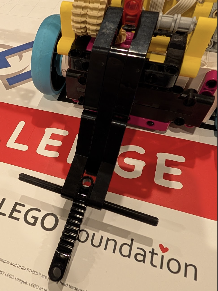
Mount Arm to Servo
Push the horn onto the servo output shaft. Rotate gently to find the end stops. Position the arm pointing forward for maximum usable range. A small screw can secure it (optional).
Connect Servo Cable
Route the servo cable through the rear slot, then through the front slot outside the sensor cables. Connect to "Servo 1" header: black to GND, red to 5V, white to I/O pin.
Testing Your Robot
Once assembly is complete, run the built-in verification test to confirm all sensors and motors are working properly.
Watch the verification test (15:40 in the video)